Proper care and feeding of the Intermatic Electronic Programmable Timer
Background
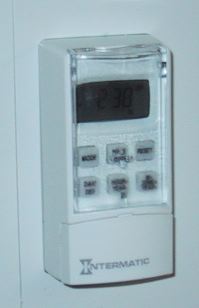
My experience is with the Intermatic SS8. This model is powered by a single AA battery and includes an astronomic clock. I’m currently under the impression that mechanical clocks to figure sunset and sunrise (astronomic function) are in the $700 range and this is the first commercial, packaged digital switch that performs the function for us mere humans.
Much of what I’m presenting probably also applies to the “simpler” electronic wall switch timers from Intermatic, such as the EI15 and EI20.
This is a very cool device since it can figure sunrise and sunset for you (given the date and longitude) and turn your lights on and off without an exterior sensor. This is particularly useful for controlling banks of exterior lighting from an interior wall switch or maybe even controlling an aquarium lamp for sunrise and sunset.
The problem is, I like many others, had the misfortune of the switching failing on short order with the dreaded “no op” “see inst” message. A quick search on the net produced nothing other than a bunch of complaints (see epinions, amazon, etc). This is not exactly a cheap light switch (the $35 range) and although it has a one year warranty by the looks of other’s experiences I’d just get another of similar quality if I went to the trouble of returning it.
I decided to open it up. Perhaps something could be addressed I thought. I had a similar experience with a Black and Decker Mouse sander: several reviews stating that it just died. Well, I popped it open and it wasn’t a big surprise to find that the failure on my vibrational sander was simply that the power wires on the motor had vibrated loose. A quick tightening and before I knew it I had literally sanded a whole wood paneled room!
Disassembly
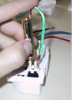
Front compartment
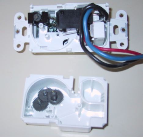
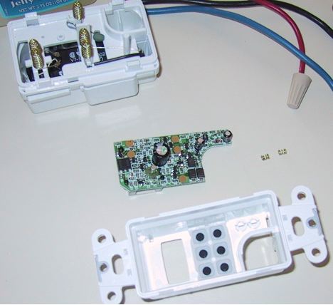
Rear compartment
The unit is fairly easy to disassemble. There aren’t any glued parts, just tabs on the sides holding things together. The front and back can be removed separately. A word of warning here, there are two small springs in the front compartment which could become easily lost.
The mechanicals
This switch is advertised as an electronic switch. We’ll that might be a little of a misnomer since technically it’s electromechanical. There is a 1.5v pager motor gear which powers a cam through gear reduction, and then a MicroSwitch to do the heavy lifting for the AC switching. It seems that the unit could have been designed with a solid state relay (are there any at 1.5V?). In any case, the fact that the whole back half of the switch case is filled with a mechanical switch apparatus isn’t that much of a surprise. This is after all Intermaic, a company that’s 100 years old and famous for it’s mechanical timers.
The failure and repair
The instruction manual states that a “no op” could be several things. Cold temperature? I just don’t see that, maybe if it’s below freezing in your house, but then you have other issues like frozen toilet bowls. Battery? Well that’s easily replaced. And the final suggestion “return for replacement”.
What “no op” really means is that when the electronic portion of the switch tries to change the mechanical switch state, it can’t. Yes, there is feedback. There is a little wire which comes back off the switch telling the electronics whether or not the mechanical switch is open or closed. It uses this to know when to shut off the cam motor when it’s changing the switch state.
It seems to me that there are two easily repairable failure modes. These are likely manufacturing issues not design issues. Therefore, I wouldn’t be surprised to see Intermatic having fixed these reliability issues in short order for future (or more recent) lots.
1. The cam part isn’t well secured to the final gear. If you have this failure then what you’re probably experiencing is a “no op” following some amount of motor sound. Here I recommend supergluing the cam to the final gear. Do this off the shaft obviously. And don’t get any in the gear’s hole.

2. The contacts aren’t connecting from the circuit card to the motor well. Here your failure would have been something more like a silent “no op” failure. I found that the bottom rung on the spring could be firmly seated in the little plastic pinch at the bottom of the plastic leg. This helps keep good contact between the relatively small motor wires and the springs themselves. Soldering the wire and spring would be a good idea too. Don’t melt the plastic post.
Reassembly
Front: You didn’t loose those small battery compartment spring contacts did you?
Rear: Put all the gears back in. Pinion sides up. It doesn’t matter which way the cam is oriented during assembly since the system has feedback as discussed above. But it’s easier to put the rear case back on if it’s at it’s lowest point with the MicroSwitch arm since they will interfere.
Testing
You can easily test your work by applying 1.5v directly to the contacts which drive the pager motor. If all is well the motor spins, and the cam operates the switch arm on the MicroSwitch.